Macdesmo and austduke
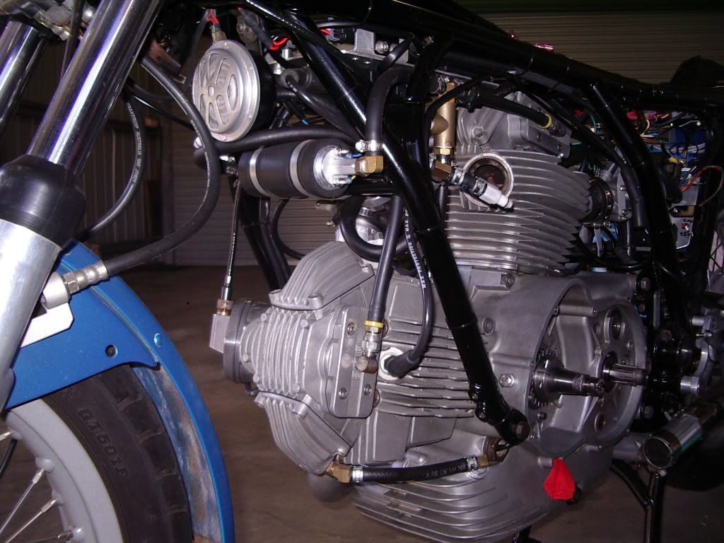
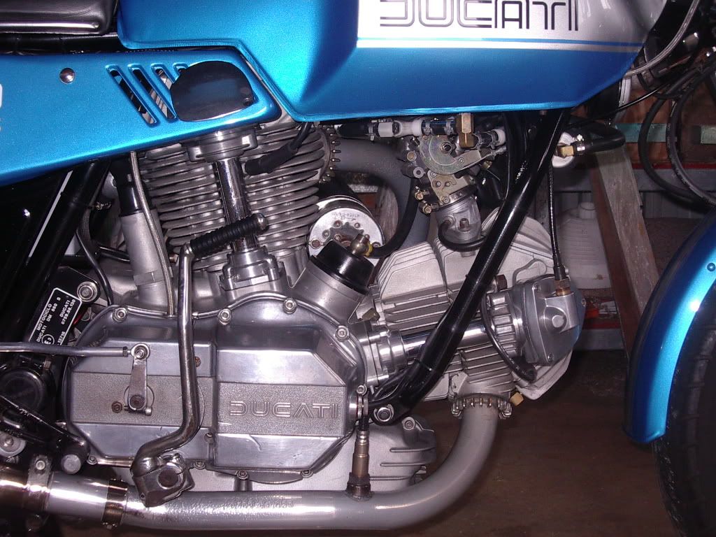
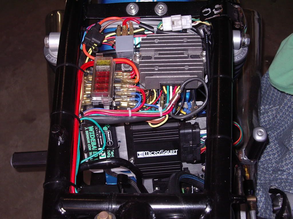
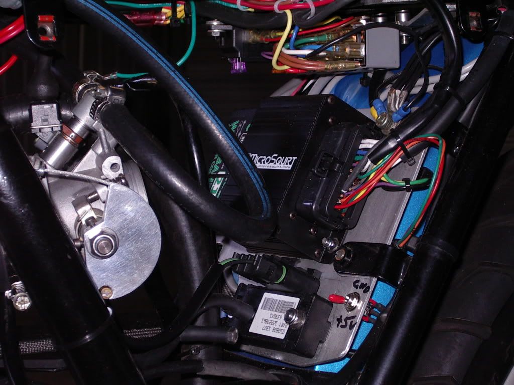
Yes, you are right, it was a lot of work but probably more mentally than physically. The secret was in the planning and understanding how the ECU worked, what it was capable of and how it could be applied to the Ducati twin. It was an iterative process to find the right setup and configuration for my engine. The fuel part of it was easy but the ignition was much more difficult. I could write a book about what had to be considered to make this happen but basically it involved things like what size throttle bodies and what injector flow rates to use (throttle bodies, injectors and fuel pump regulator transplanted from 2003 Ducati Monster 800). These suited the tune of my heads perfectly. Another big issue was fuel supply because I didn't want to modify the tank to fit an intank pump. As a result I was forced to use an automotive inline pump which usually draw too much current an flow much more than is needed for motorcycle engines. The answer was to use a PWM motor speed controller to slow the pump down therefore decreasing the flow rate from 160 to 45 LPH.
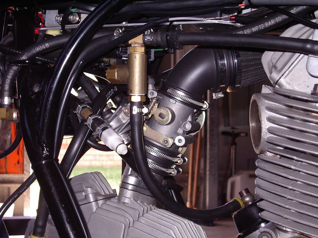
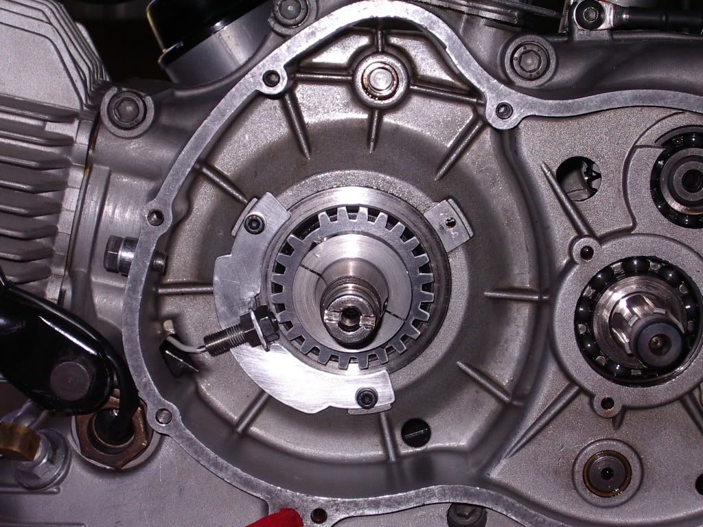
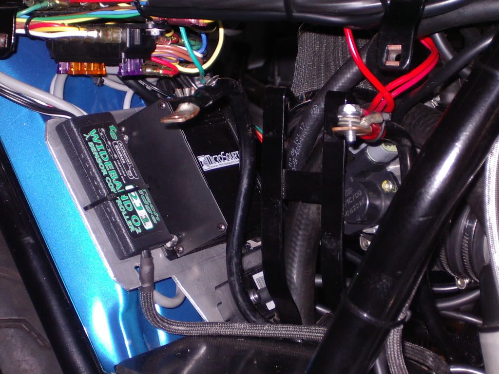
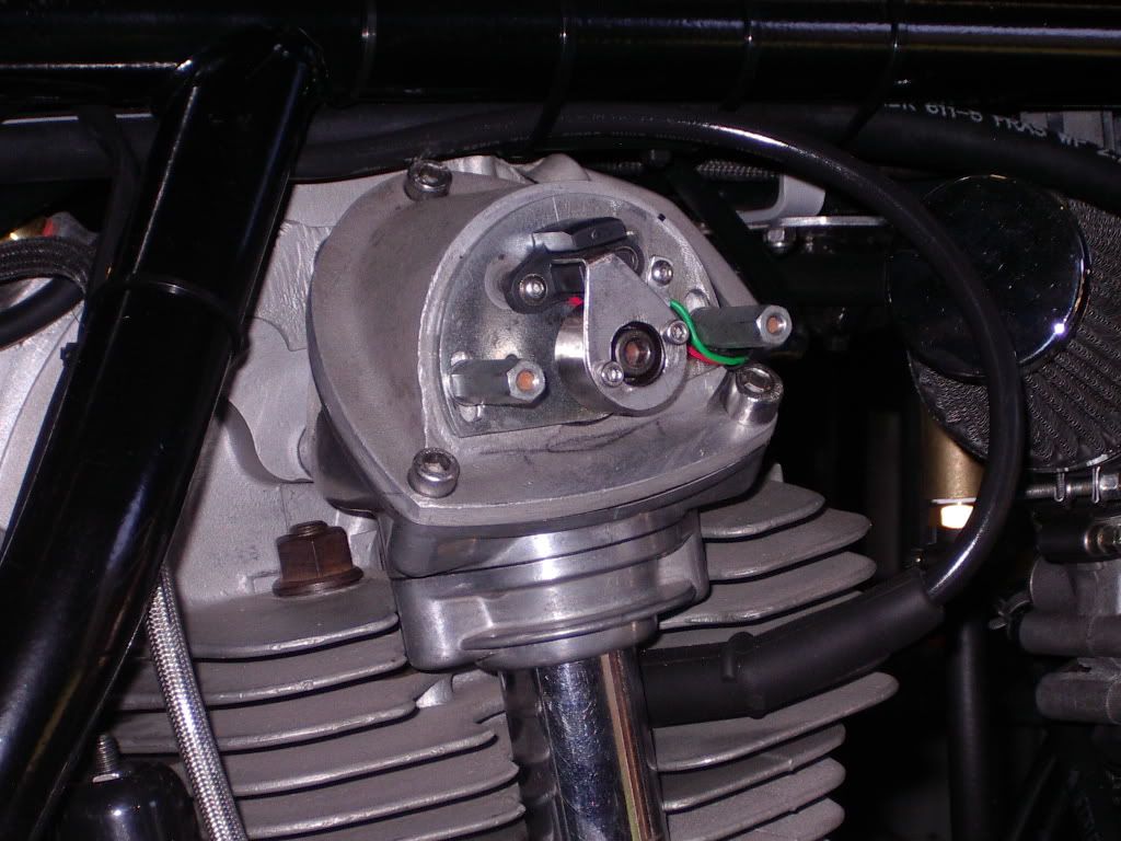
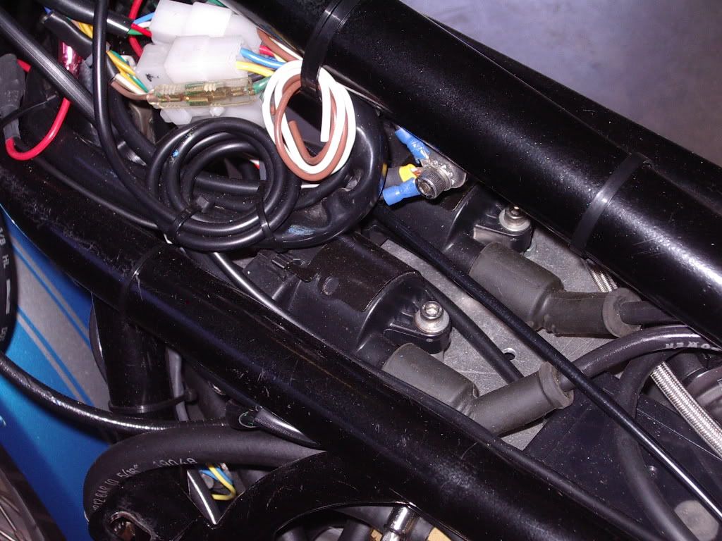
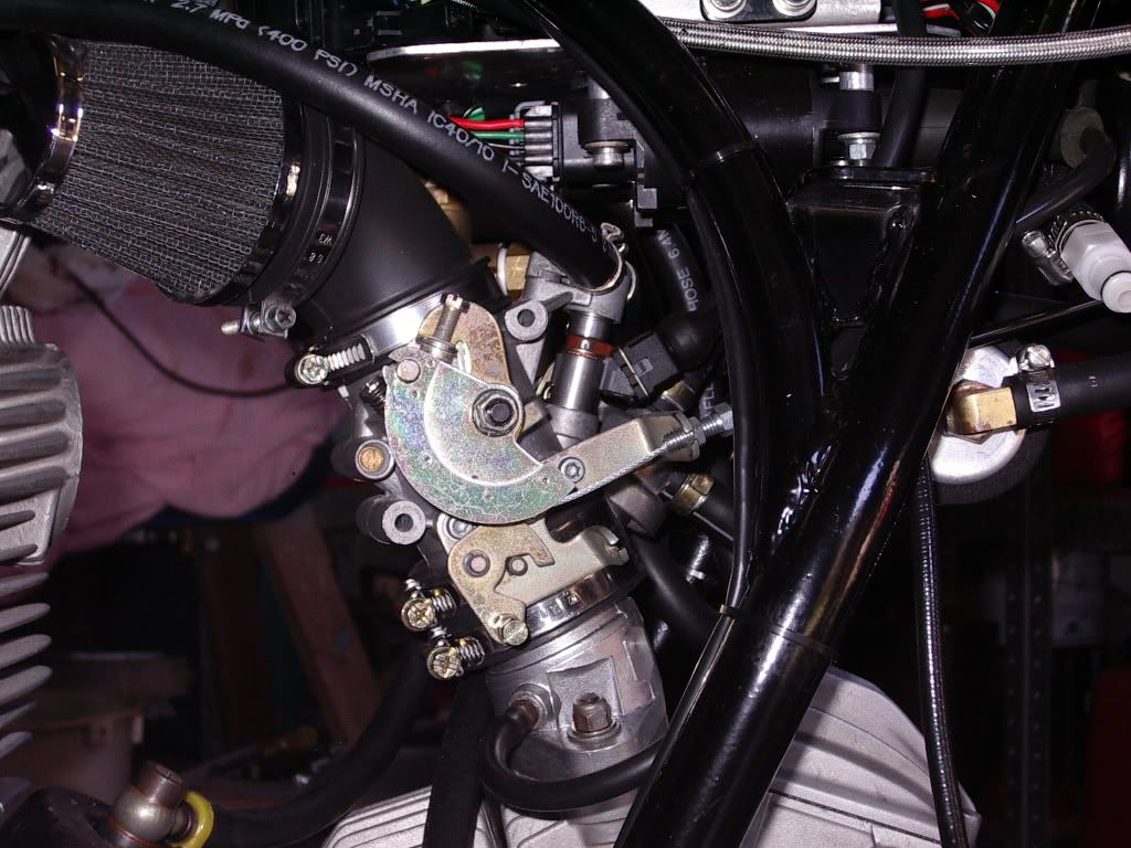
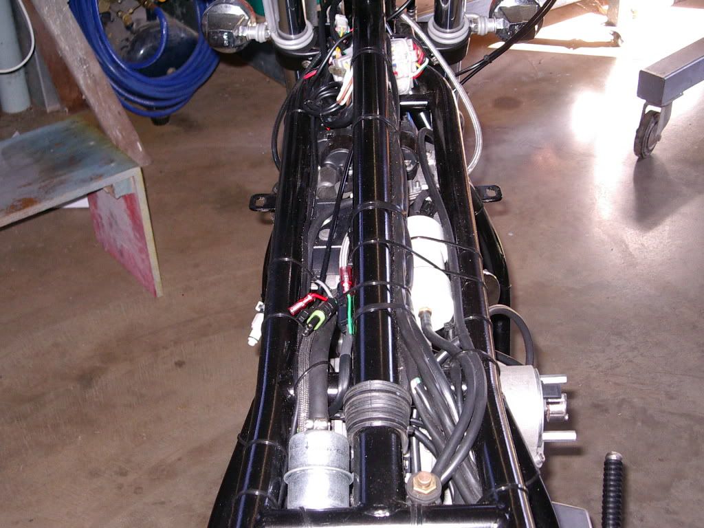
Sensors used include a VR magnetic speed sensor on the crankshaft for ECU tach input and ignition timing, a coolant temperature sensor installed in the rear cylinder rocker cover to measure engine temp, an intake air temperature sensor installed under top triple clamp so it doesn't heat sink from the engine, a throttle position sensor operating on the rear cylinder throttle body, a manifold absolute pressure sensor measuring manifold vacuum from both cylinders via a small plenum chamber for smoothing, and a wideband O2 sensor installed in front cylinder header pipe to measure AFR for closed loop EGO control. Mostly this is used for tuning though.
Ok I've probably bored you already with this stuff but believe me this is only scratching the surface. Ausduke, I had to upgrade the alternator and regulator to meet the extra load imposed by the fuel pump, four high energy smart coils, high impedence injectors and the heating element in the O2 sensor. I transplanted a 350 watt alternator from a 1998 Ducati 916. The stator fitted without drama but the rotor was too wide and had to be machined carefully to avoid weakening the structure. This combined with the regulator off a similarly late model Ducati has worked perfectly to overcome a potentially big problem.
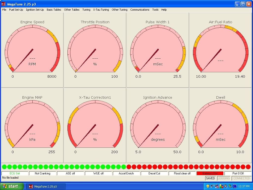
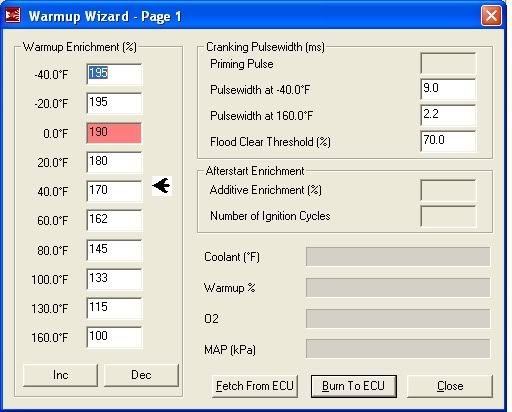
So, how does it go and what differences do I notice? Starting is effortless (electric start, though I have kick started with this setup). I control the intake air on cold starting manually by using the throttle stop and after hitting the button it fires straight up and holds the engine speed as determined by the throttle position. Even before getting any where near full temp it will hold a steady 1000 rpm idle and this does not falter no matter how long it idles for. Considering that I haven't yet tuned the acceleration enrichments, the throttle response on quick opening is excellent (compared to EFI Monsters that I have sampled which can be vague and fluffy in this area). Throttle response across the board is impressive and I'm comparing this to the 38mm flatslide Mikunis that this engine was using prior to EFI. The response of the Mikunis was very very good. In general the breathing of this engine is noticeably improved with the 45mm chokes but keep in mind that these heads are a long way from standard. Given the tune of this engine, the most noticeable difference for me is how the EFI has smoothed it out.
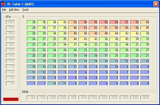
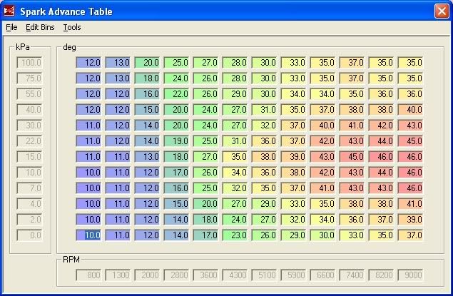
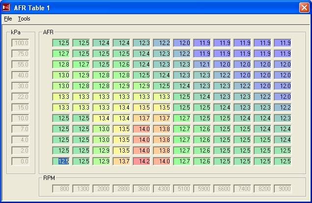
The other big difference is tunability. With access to a 12 X 12 fuel map, a 12 x 12 spark advance map, a 12 X 12 AFR map and a sh**tload of other configuration stuff, the sky is the limit for tuning. The real gains to be made with this setup are in spark advance tuning and that will probably mean some dyno time. To say that I'm like a dog with two dicks at the moment is an understatement.
Anyway you have probably been bored sensless by now so I'll leave it at that.
Paul