Does anybody out there know the details of this inductor pickup?
I've depotted my non-working unit and find a coil of 47 ohms resistance, a 1N-series half-wave rectifier diode and a 330 ohm resistor wired in parallel to the coil.
I'm suspecting one or more shorted turns in the coil, as I'd expect closer to 500 ohms, also not real sure that the 330R is original (it's been "repaired" previously).
The Ducati factory don't seem inclined to reply to historic queries, so any info would be very much appreciated.
Ciao
Ducati Elettronica ignition trigger '72-'74 singles
-
Craig in France

- Paso 906
- Posts: 974
- Joined: Tue Mar 23, 2004 3:58 pm
- Location: Montpellier, France
Re: Ducati Elettronica ignition trigger '72-'74 singles
Hi Bill,
In 2008 I had a pick-up rebuilt by this company in the UK who might be able to advise, assuming they still have the details of what they found/did.
http://www.westcountrywindings.co.uk/
My contact was Michael Simmons.
P.s The other people who might be able to help is the Amici dello Scrambler. But Ducati itself won't have a clue . As well as their general ignorance about much of their own history, Ducati Meccanica and Ducati Elettronica were already 2 separate companies by then.
P.p.s A similar looking DE pick-up was used on the Morini 3½. But whether they're similar inside electronically, I don't know.
HTH
Craig
In 2008 I had a pick-up rebuilt by this company in the UK who might be able to advise, assuming they still have the details of what they found/did.
http://www.westcountrywindings.co.uk/
My contact was Michael Simmons.
P.s The other people who might be able to help is the Amici dello Scrambler. But Ducati itself won't have a clue
P.p.s A similar looking DE pick-up was used on the Morini 3½. But whether they're similar inside electronically, I don't know.
HTH
Craig
Last edited by Craig in France on Sun Nov 23, 2014 3:36 am, edited 1 time in total.
Re: Ducati Elettronica ignition trigger '72-'74 singles
Thanks Craig - I'll check that link out :-)
Ultimately it's going to involve a total dismantling I guess, so I'll be able to measure the length of the winding, although I'd rather avoid that if possible lol
Bill
Ultimately it's going to involve a total dismantling I guess, so I'll be able to measure the length of the winding, although I'd rather avoid that if possible lol
Bill
Re: Ducati Elettronica ignition trigger '72-'74 singles
The singles use the same red transducer box as the bevel twins? I assume there are two trigger coils, a static for starting and a full advance.
I unpicked a twin stator and this is what I got, retard trigger coil 652 turns 0.15mm wire 18.8 ohms, advance coil 330 turns 8.8 ohms, The charge pump coils were ok so I did not rewind them but they have a lot of turns and run to 280ohms.
Jock
I unpicked a twin stator and this is what I got, retard trigger coil 652 turns 0.15mm wire 18.8 ohms, advance coil 330 turns 8.8 ohms, The charge pump coils were ok so I did not rewind them but they have a lot of turns and run to 280ohms.
Jock
Re: Ducati Elettronica ignition trigger '72-'74 singles
From what I've gleaned from the 'net, there's only a single winding on the induction coil and the advance curve is generated by the rate of magnetic flux buildup relative to revs. I'm not an electronics engineer, so considering that Ducati in those years were pretty well versed in the KISS principle I'll go with that for the meantime.
On dissasembly, I tried to measure each fragment of wire I unravelled - with laquered assembly, not always a straight unwinding; sometimes short lengths came away in parallel, ect but the total of the very fine fragments in the bucket was over 30 metres. I'm guessing around 40, allowing for my hamfisted reverse engineering :-)
Using the specs for 0.1 mm copper wire, 40 metres should give around 85 ohms resistance through the coil itself.
When I dismantled my trigger there was a 330 ohm resistor connected in parallel to the coil, along with a 1N-series diode to ensure DC current to the transducer (or ignitor as the Jap brands call it).
Using the usual calcs, that should give a total resistance through the trigger unit of somewhere around 70 ohms. I vaguely remember a bit less than 100 when it was still working, but that was with a cheap meter and the dry joints etc that led to the eventual failure may have been there.
Next step is to rewind the bugger - tdious I'm sure :-)
Re: Ducati Elettronica ignition trigger '72-'74 singles
I have a 450 Ducati Electronica CDI system that was working when I removed it. The ignition was fine, I replaced it with an Electrex system due to Stator battery charging issues, the ignition was fine. Are there some measurements I can take for you?
Kev
Kev
Re: Ducati Elettronica ignition trigger '72-'74 singles
Thanks Kev, that would be great!
If you could just measure the resistance across the output leads it's a simple calculation after that. It'll appear open circuit in one direction,due to the diode but we expect that.
Cheers,
Bill
If you could just measure the resistance across the output leads it's a simple calculation after that. It'll appear open circuit in one direction,due to the diode but we expect that.
Cheers,
Bill
Re: Ducati Elettronica ignition trigger '72-'74 singles
Hi Bill,
Based on what you've found by unpotting the pickup, this doesn't seem to make sense...
Here's my pickup unit...

Resistance one way on 20 MOhm test....open circuit...

The other way..5+ megaOhms on a 20 MOhm test...
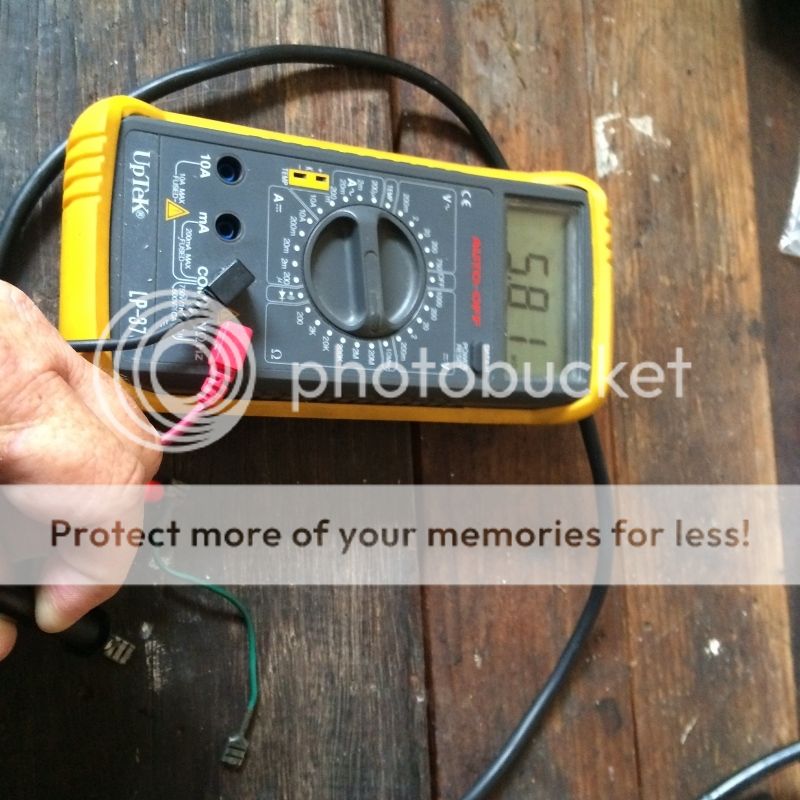
I tested it with another gauge...same result. I didn't change it myself, so it is possible it wasn't working, but I'm pretty sure it was.
Kev
Re: Ducati Elettronica ignition trigger '72-'74 singles
Thanks Kev - you're right, that's a really strange result. Puzzling.
Thinking back, when my unit had definitely failed there were sometimes "ballpark" resistance readings going open circuit within about a second and sometimes several megohms. Initially I thought maybe a capacitor somewhere in the mix, but on depotting certainly not.
I'm starting to suspect the first problem may have been due to shorted turns in the winding, then the "professional repair" may have made it worse by introducing a dry joint or two. And maybe the repairer's repotting resin may have been slightly conductive? No way of telling on that, 'cos it's all in the bin long ago :-)
I've just assembled the basic framework for a manually powered rewinding machine, so with a bit of luck might get to start rebuilding the coil next week (race meeting on this coming weekend, so not much work will get done).
The plan is to wind enough on to fill the armature, then check the output voltage with the diode installed and adjust the parallel resistor's value to deliver 0.7VDC or so. The aftermarket thyristor I'm using works on a gate voltage of 0.5 - 1.2 (from memory). Watch this space, as they say :-)
Bill
Re: Ducati Elettronica ignition trigger '72-'74 singles
Hi again Kev,
'Scuse me for asking, but what's the green wire connected to? It looks like a link wire of some sort with nothing on the other end?
Cheers,
Bill
'Scuse me for asking, but what's the green wire connected to? It looks like a link wire of some sort with nothing on the other end?
Cheers,
Bill
Re: Ducati Elettronica ignition trigger '72-'74 singles
Hi Bill,
It's not clear in the pictures, but one of the wires from the pickup has two terminals on it, with the tail wire the short green one. I'd need to have a look at the wiring harness to trace where it's going. It's not exactly clear from the wiring diagram as there appears to be three wires on a common connection to the CDI/Coil unit.
Kev
It's not clear in the pictures, but one of the wires from the pickup has two terminals on it, with the tail wire the short green one. I'd need to have a look at the wiring harness to trace where it's going. It's not exactly clear from the wiring diagram as there appears to be three wires on a common connection to the CDI/Coil unit.
Re: Ducati Elettronica ignition trigger '72-'74 singles
Btw....I also saw when measuring a declining resistance from about 8MOhm before it stabilised which also looked like a capacitor in the circuit.
Kev
Kev
Re: Ducati Elettronica ignition trigger '72-'74 singles
Hi Kev - thanks for that, it's been so long since I've seen the "original" set-up I'd forgotten about the grounding wire on the negative lead from the trigger.
I gave away the road equipment on mine 20-odd years ago when I'd planned to make it a track bike, so connected that to a handlebar kill switch.
Now that she's back to road trim with an aftermarket headlamp , things are changing again :-) - including a Jaycar "transducer" as an alternative.
That "spike" and fade is a puzzlement though as there's definitely no capacitor there. Could the applied voltage from the multimeter be inducing an emf in the coil for a short time? As I've said, I'm no electronics engineer, so that's a total guess.
Cheers,
Bill