1974 GT Alternator Mod
Posted: Thu Jan 12, 2012 12:51 am
As per normal the winter has given me a little time to tinker with the bike. I took it upon myself to fix this wiring/ charging thing once and for all.
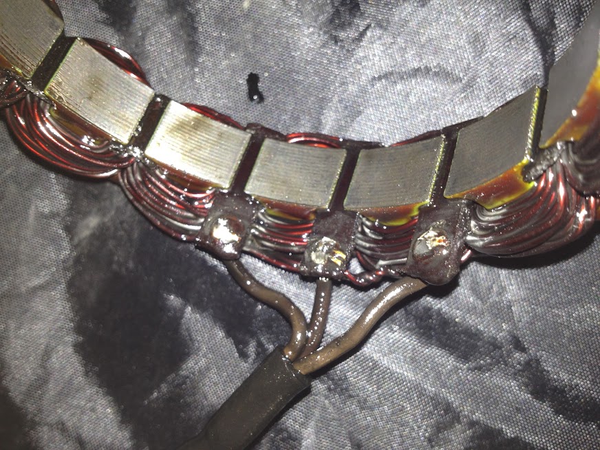
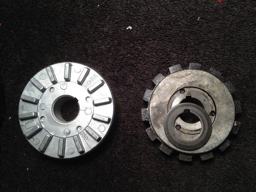
I cleaned up the wiring, changed a few things around and then I started thinking about the charging system. I have a new rotor that I will be installing but I am also thinking about the stator. The stator from the bevel is centre tapped due to the old rectifier circuit used. That means that only half the output voltage is used when rectifying in the original design. I found some comments by a guy name James de Raeve who wrote about this fix.
When using a modern bridge rectifier that only requires two inputs from a single phase stator. The excess voltage will just get turned into heat by the regulator. So why not modify the stator to use the coils from the center tap in parallel rather than in series. This will half the output voltage but it will double the current available.
Stator Before:
____|--------yellow(a)
/
\
/
\____
____|--------red
/
\
/
\____|--------yellow(b)
The following would be the mod to the stator
1.Disconnect one copper wire from the windings from the center tap.
2.Determine which yellow wire(a) and the disconnected copper from the windings form an open circuit.
3 Now attach that copper wire to the alternate yellow(b).
4. There should now be one copper wire left at the center tap from the windings this can be attached to the other yellow(a) 5. the center tap red can be ignored and that wire discarded
6. use these two yellow in a two wire bridge rectifier.
Stator After:
_______|--------yellow (a)
/ /
\ \ ________ center tap is no longer used
/ /
\_\______
-----------|--------yellow (b)
Thoughts? Downside other than wrecking my stator when I do the soldering.